SDC has investigated the AIST torsional design approach in Section 7.15.1 of Technical Report No 13 where a modified lateral load, Q(eff), is determined to check for lateral bending of the top flange. SDC finds that the AIST approach provides a conservative torsional analysis of a doubly symmetrical open section crane girder. However, it may not be conservative for a crane girder with a singly symmetric or unsymmetrical cross section.
The SDC approach is to perform a full torsional analysis of the singly symmetric and unsymmetrical crane girders using Warping Torsion Theory. The torsional analysis starts by calculating the torsional section properties including the warping constant and beta value. We then calculate the warping normal and warping shear stresses by determining the second and third derivatives of the angle of twist for the appropriate end condition (pinned or fixed). The torsional analysis includes the effects of any crane rail float or offset.
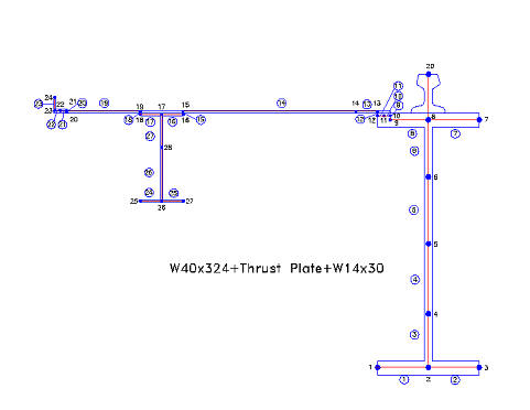
A typical unsymmetrical crane girder found in many steel mills is shown below.

The thrust plate and back-up beam provide stiffness to accommodate the lateral thrust loads. The girder section properties need to be resolved about the principal axis of the crane girder as part of the torsional analysis. The principal axis is innate to any girder cross section where the greatest moment of inertia is calculated along the strong axis and least moment of inertia is calculated along the weak axis. The principal axis corresponds with the rectangular axis for a doubly symmetrical cross section. This is one of the reasons why the AIST approach to torsion is conservative.
The principal axis of the W40x324 girder with the thrust plate and a W14 back-up beam is calculated to be approximately 21 degrees from the rectangular axis. The rotation from the rectangular into the principal axis causes large horizontal shear stresses in the top flange of the girder and elements used for lateral stiffness.
Torsion-resistant crane girders need to be sized with the proper balance between its length (L) and its torsional inertia property ratio (Beta). Both the Saint-Venant torsional constant (J) and the warping constant (Cw) need to be determined to calculate the (Beta) value. The optimum cross section for a torsion-resistant crane girder needs to have its (Beta*L) product fall in the torsional response range of “mixed torsion” between dominating warping torsion and dominating Saint-Venant torsion. If the (Beta*L) value is not optimized, the design of a shorter girder tends to be controlled by warping while a longer girder tends to be controlled by Saint-Venant torsion.
The (Beta*L) value for the girder shown above is 1.37 which means that the girder behavior is warping dominant but not governed by pure warping torsion. A (Beta*L) value between 2.0 and 5.0 is required to be in the more desirable “mixed torsion” range. The (Beta*L) value would need to be > 10.0 to be dominated by pure Saint-Venant torsion. It is our experience that most unsymmetrical girders fail due to rotation about their shear center where they become plastically deformed to the point where the crane cannot bridge down the runway without excessive rail wear.
For reference, please go to the CRANE GIRDER PRO Calculation Output for a W40x324 girder with a 3/8″ thrust plate and W14x30 back-up beam. This type of girder is not specifically addressed by AIST Technical Report No.13.