SDC has been inspecting crane girder runways since 1988. Some runways may have several hundred structural deficiencies if the low priority items are included. Structural repairs are normally only made to the very high priority items. The highest priority items are crane girder weld and base metal cracks. Sheared girder tie-back and diaphragm bolts are the next level of priority along with crane rail and crane girder alignment. Crane rail and runway alignment surveys are required to address worn crane wheel and worn rail issues.
Crane girder failures almost never lead to total collapse. However, some of the cracks could lead to collapse if not immediately repaired. SDC finds severely deficient crane girders on a regular basis. Examples of severely deficient crane girders are provided below.
Crane Girder Warping Failure
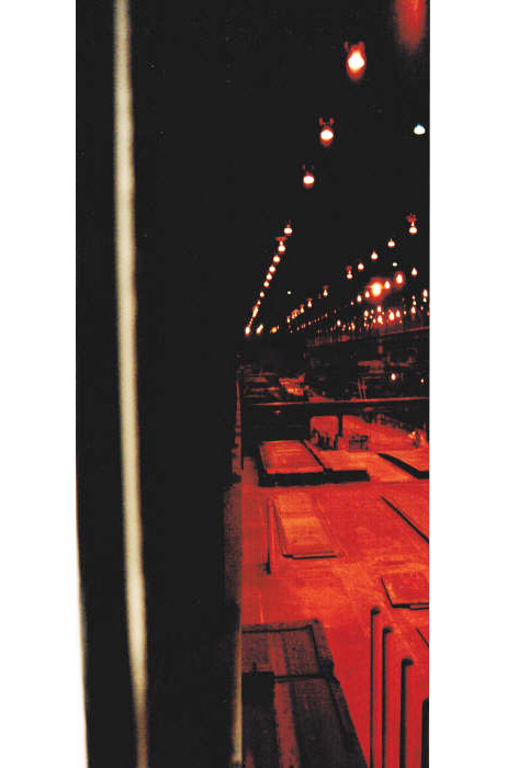
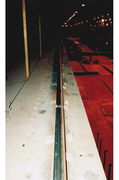
Photographs #1 and #2 show a 112 ft. long 11’-2’ deep girder that is warped 5”. The inward bow in the bottom flange can be seen in Photograph #1. Photograph #2 shows the wear on a new crane rail. The top flange and backup truss are also warped outward (Not Visible). The crane rail could not lay flat on the requiring girder replacement with a torsion resistant girder with a 5” thick top flange. This a text book torsional failure.
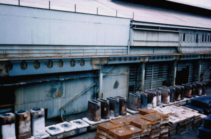
Photograph #3 shows a Mold Yard where ingot molds are removed from the ingots. The 25 ft. long crane girders are built-up sections constructed from angles and plates. The girders have a thrust plate connected to a back-up truss. The crane girders became warped causing the crane jump off the crane rail. This is a text book torsional failure that was repaired by welding plates to both sides of the girders at the tips of the top and bottom flange.
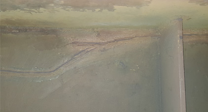
Photograph #4 shows typical girder base metal and fillet weld cracks at the top flange. The cracks start at the intermediate stiffener and extend diagonally down the girder web. Some girder webs buckle when the crack depth from the top flange is 9”.
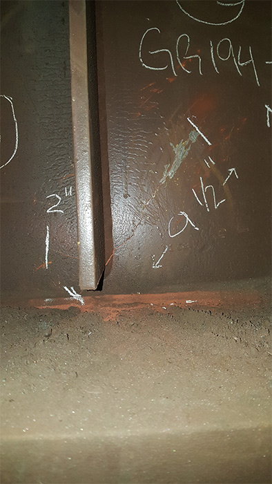
Photograph #5 shows a less typical girder base metal and fillet weld cracks at the bottom flange. The cracks start at the intermediate stiffener and extend diagonally up the girder web. Since this crack is in the tension zone it can quickly propagate up the web.
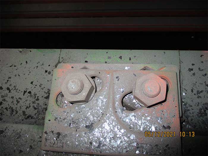
Photograph #6 shows a unique top flange crack that extends down the girder web. The crack starts at the weld for the crane rail clip and is due to fatigue from the torsional loads. This type of crack is also found at bolt hole locations.
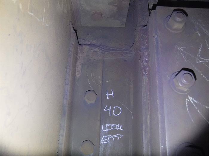
Photograph #7 shows a base metal crack in the building column that is in line with the crane girder diaphragm. The diaphragm ties the girder back to the column flange. The column flange and column web are cracked. The outside flange of the column is not deficient but the backup beam has a crack.
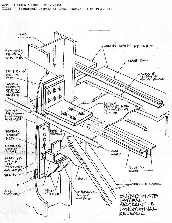
Photograph #8 shows a new building truss connection to the column web. The 56 ft. long crane girder was transferring the crane runway longitudinal and lateral loads to the truss and not to the traction bracing and diaphragm plate. The WT24 connection from the truss to the column web was shearing throughout the mill. The new connection allows the building truss to slide. New crane girder tie-backs with slotted holes were also installed.
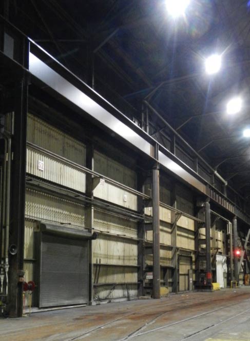
Photograph #9 shows new 50 ft. long torsion and fatigue resistant replacement crane adjacent to the original girders.