Since AIST Technical Report 13 was issued in 2003, the American National Standards Institute /American Institute of Steel Construction (ANSI/AISC) 360-10 steel design code has been revised several times. In 2005, the 13th edition of the AISC Manuel of Steel Construction which includes the Specification for Structural Steel Buildings was published. Three (3) more editions of the AISC manual have been issued since 2005. These newer AISC steel design codes contain significant updates that affect the design of crane girders, including updates in evaluation of fatigue.
2005 AISC Specification
The 2005 AISC specification integrated both the Allowable Strength Design (ASD) and Load and Resistance Factor Design (LRFD) Specifications into a single set of rules for the design of steel structures. The new specification unified the design standards with the most current knowledge and design practice that focus on strength rather than on stress. One notable change is that the term “Allowable Stress Design” in the 9th edition has been officially changed to “Allowable Strength Design.”
For crane girder runway girder design, the section regarding plate girders found in the 9th edition of the code was eliminated. Section F12 was added to cover the design of unsymmetrical structural shapes such as built-up plate girders.
The current AISC specification is basically unchanged regarding the design of crane girders. However, since 2005 an interesting remark is found in Section H3.3 of the Code Commentary. This is the only area of the code where crane girders are mentioned. This section deals with Non-HSS Members Subject to “Torsion and Combined Stress” and crane girders are subject to large torsional stresses. AISC refers to Design Guide 9 “Torsional Analysis of Structural Steel Members” for a complete discussion on torsional analysis of open shapes. One of the big challenges structural engineers face is that AISC Design Guide 9 does not discuss how to calculate the warping constant (Cw) that is critical in the torsional analysis. The design guide also does not provide expressions for normalized unit warping (ωn – a sectoral coordinate for determining the Warping Static moment(Sw)) and static moment (Sw) that are critical in torsional stress analysis. There is almost no useful information in AISC Design Guide 9 for addressing issues for crane girders having unsymmetrical cross sections.
Section F12 applies to all unsymmetrical shapes except single angles. Structural engineers must determine the nominal flexural strength, Mn, for limit states of yielding, lateral torsional buckling, and local buckling. The AISC Code goes on to state that the local buckling stress should be determined by analysis. Other than following the compact criteria under Section B4, the problem structural engineers face is that the code does not provide specific guidance as to how a local buckling analysis should be performed for unsymmetrical sections.
Research by SDC has yielded no papers or other printed material on the subject for crane girder application. Additionally, SDC questions whether lateral torsional buckling criteria should be applied to unsymmetrical crane girder cross sections. The reasoning for this opinion is due to the tendency of an unsymmetrical cross section to rotate about its principal elastic centroid under flexural bending. This is true even for the girder’s own dead weight. An unsymmetrical member is most stable when it bends about its principal elastic minor axis as its compelling axis of bending. However, in SDC’s opinion the typical flexural bending acts only as a trigger that would be immediately taken over by rotation about the shear center long before the section can settle into its most stable (comfortable) axis of bending. Therefore, torsion always exists in unsymmetrical sections unless the applied load resultants pass through the shear center.
Unsymmetrical Crane Girders
Most crane girders in older steel mills are designed with unsymmetrical built-up girders or singly symmetric girders constructed from wide flange sections with welded cap channels. Figure 1 shows some of the unsymmetrical and singly symmetric crane girder cross-sectional shape combinations found in the steel industry. The current edition of the AISC Manual of Steel Construction tabulates some of the properties of wide flange shapes with cap channels. However, their torsional properties are not included in the tables. The torsional properties are difficult to calculate. The realistic torsional behavior of the girder cannot be assessed without calculation the warping constant (Cw), normalized unit warping (ωn) for warping normal stress and the warping static moment (Sw) for warping shear stress.
SDC has developed a paper found on this web site which shows a 17-step procedure for determining the warping constant for any arbitrary open-shaped crane girder cross section. Calculating the warping constant (Cw) requires engineers to properly predict the shear flow pattern. It is easy to make a mistakes since the shear flow in some unsymmetrical crane girders is not obvious. SDC has pioneered an algorithm to automate and verify the shear flow scheme in girders. The scheme needs to result in zero warping stress at the terminal end of the girder cross section. SDC can now automatically calculate the torsional warping constant (Cw) of any arbitrary sectioned open-section girder.
It is SDC’s experience that unsymmetrical crane girders often act in unpredictable ways. In 2000, SDC designed replacement crane girders for a mill building that was originally designed with rolled, wide flange sections connected with thrust plates to a backup channel. The replacement crane girders heavier, doubly symmetric plate girders that were connected to the original thrust plates. SDC was surprised to learn that many of the backup channels connected to the heavier plate girders through the thrust plates subsequently sheared a few feet from the column connections. It was interesting to observe that none of the backup channels sheared that were connected to the original rolled, wide flange girders. After CRANE GIRDER PRO became available, a stress check was performed on the new girders and the program predicted the backup channel overstress in a zone near the girder end.
SDC has found that back-to-back (or side-by-side) crane girders on adjacent crane bays that are connected with a common thrust plate have another issue. The shear center of this combined girder section can be located several feet above the thrust plate in the center of the upside-down “U” shape. The rotation of the combined girder about the shear center causes additional girder stress, along with tensile loads in the crane girder tie-backs and seat bolts. The tensile loads and associated prying action forces are most likely not included in the original design of the connections. Rotation about the shear centers of unsymmetrical crane girders could be the root cause of many tie-back and girder seat bolt failures.
AISC Section F12: Crane Girder Analysis
As noted previously, the AISC code states that the local buckling stress should be determined by analysis in Section F12 of the code. Additionally, SDC questions whether lateral torsional buckling criteria should be applied to unsymmetrical crane girder cross-sections. SDC’s approach is to perform a mechanical-type stress analysis, only addressing the yield stress to satisfy the requirements of Code Equation F12-2. The local buckling stresses are not a concern if the “effective” width-to-thickness ratios of the compressive elements of an unsymmetrical crane girder are limited to the values shown in Table B4.1a and B4.1b of the AISC code.
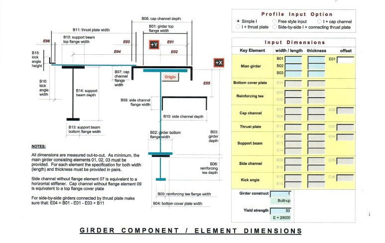
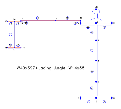
SDC models the entire crane girder cross-section as an unsymmetrical flexural member into our proprietary CRANE GIRDER PRO computer program. CRANE GIRDER PRO is written in Microsoft Access to perform the difficult task of managing a remarkable amount of data involved in performing a full torsional and fatigue analysis of the crane girder. The analysis is above and beyond AISC Design Guide 9 and generally follows the Bethlehem Steel Design file 13-A-1, 1964. Figure 2 shows the structural model for a W40x397 girder tied to a back-up beam with lacing angles. The lacing angles were modeled into the program by using an equivalent 0.08-inch thick thrust plate to generate the structural and torsional properties of the girder. The 0.08-inch thickness represents the area of a 36-inch-long lacing L4x4x3/8. Hand calculations are subsequently performed to convert the thrust plates stresses back into compressive loads in the lacing angles.
CRANE GIRDER PRO uses nodes and elements as any other structural analysis program to determine the geometry of the girder cross-section. The difference is that the cross-section of the structural member is being coded, and not the beams and columns of a building frame. Nodes are also defined at all bolts, welds or other attachments where fatigue stresses need to be calculated. The elements to the left of Node 11 are considered ineffective for strong axis bending in accordance with Table B4.1a.
AISC Design Guide 9 does not provide any methodology for calculation the torsional properties and has omitted the mathematical expressions for the derivative of the rotation function. Therefore, it would be very difficult to adopt Design Guide 9 as a template for solving crane runway girder problems. SDC uses an approach similar to one pioneered by Dr. Theodore Galambos to calculate the torsional warping constant (Cw). SDC has gone the next step to calculate the warping static moment (Sw) for warping static shear stress to validate the shear flow scheme. The correct warping constant (Sw) will yield zero warping static moment at the terminal ends of the crane girder cross-section. Additional nodes and elements are input into SDC’s crane girder cross-section model to determine stresses at various fatigue hot spots.
After the torsional properties of the crane girder cross-section are determined, AISC Design Guide 9 would normally be followed to determine the St. Venant torsion stress, warping normal and warping shear stresses. The problem is that AISC Design Guide 9 provides mostly design graphs for calculating the torsional stresses without giving the most needed response function derivatives. The derivatives allow the user to automate or fine-tune the results for design optimization purposes. Not only does it take time to use the graphs, but also the accuracy of the results highly depends on how precisely one can read between the grids and curves. CRANE GIRDER PRO has hard-codes the torsional response functions for the torsionally pinned-pinned, fixed-fixed, and pinned-fixed end conditions. It needs to be pointed out that a flexure/torsional influence-line analysis needs to be performed for each wheel of the crane as it bridges down the crane girder.
The mechanical-type stress analysis to determine the overall stress state at any given node is performed by combining the longitudinal and shear stresses (due to flexure and/or torsion). CRANE GIRDER PRO combines the stresses by taking the sum of the squares (SRSS) of each stress type and comparing the resulting SRSS stress to a 0.6Fy allowable for (ASD applications). However, care must be taken to calculate and compare the stresses for the proper load combinations. CRANE GIRDER PRO checks stress by an exhausting results from 12 different stress combinations, since crane girders are subject to stress reversal and different lateral load factors (per AIST Technical Report13) for fatigue and non-fatigue load cases.
The maximum fiber and shear stresses occur at the different points along the span of a crane girder. CRANE GIRDER PRO calculates the total stress state in user-defined zones along the girder span. It is not known if the maximum total stress at any given node is located at mid-span, near the end, or in a transitional area. Crane girders without intermediate stiffeners are generally subdivided into either three or five zones, depending on the length of the girder and locations where critical stresses may occur. The end zones are usually a few feet long, while the center zone includes most of the girder length. It is important to note that the maximum fiber stress is not located in the area of the maximum shear stress. Numerous computer runs are made to adjust the zone length that produce the optimized combined stress. Enveloping the maximum stresses using a single zone always leads to a conservatively design girder. This may be acceptable for a new crane runway. However, this simplified, single-zone approach is detrimental for requalification of an existing crane girder being upgraded for a heavier crane loading. Numerical accuracy is important when designing or upgrading the load capacity of a crane girder. Accurately determining the state of stress at a fatigue point is difficult with hand calculations.
Conclusion
The AISC specification acknowledges the complex structural behavior of unsymmetrical crane girders in Section F12. The behavior of unsymmetrical crane girders is unpredictable. However, with CRANE GIRDER PRO, Structural Design Corporation can now perform very detailed structural analysis of unsymmetrical crane girders and better understand their behavior. SDC has learned that many of the crane girder structural deficiencies found in steel mills are due to crane girder section geometry being unsymmetrical. The crane girder deficiencies include weld and base metal cracks, along with the additional tension loads on crane girder tie-backs and seat bolts that are currently not accounted for.
Acknowledgements
SDC is grateful to Professor Theodore Galumbos from the University of Minnesota for his assistance in clarifying the requirements of the AISC Steel Construction Manual, along with helping to clarify the process for calculation of the torsional warping constant (Cw).

